Thursday, February 28, 2019

Theory of Thermocouple Operation

  • A thermocouple is a simple temperature measurement device consisting of a junction of two dissimilar metals.
  • Contrary to popular belief, the voltage measured (and converted to a temperature) is not a function of the junction alone. Rather it is the temperature difference (or gradient) between the junction (or hot), end and the reference (or cold), end.
  • A thermocouple circuit whose junction and reference are the same temperature will measure no temperature (0V).
  • If this were not true, we could create a self-sustaining voltage generator using a thermocouple, a resistive load and an oven, that would require energy only at start-up.
Theory of Thermocouple Operation

The temperature equation for the simplest of thermocouple circuits shown above is:

T = Tjunc – Tref

Where T is the desired measurement, Tjunc is the hot junction temperature and Tref is the reference
temperature, or cold end.

For simplicity’s sake, we use T, Tjunc and Tref here, but in reality these are voltages that are later converted to a temperature.

Cold Junctions
Theory of Thermocouple Operation

The temperature equation for this diagram is:
T = Tjunc – Tcj1 – Tcj2

A fundamental problem when using thermocouples is the fact the when connected to a measurement device (voltmeter or TC meter), a third metal is introduced (the connecting terminals), and two more thermocouple junctions are created. These adversely affect the temperature being measured. The new, (and unwanted), junctions are referred to as “cold junctions” and need some type of “cold junction compensation” in order to make accurate measurements.

In addition to the added variables in the previous equation, the temperature of the cold junctions
(reference end), is still not known. The following rule helps things out a bit:
  • If both TC connections to the meter are of the same metal or alloy, they cancel each other and have no affect on the measurement, as long both connections are at the same temperature (which can be assumed).
Since the definition of a thermocouple states that it must be of dissimilar metals, a second thermocouple must be introduced to the circuit to achieve this. This was the first of what is commonly called “cold junction compensation”

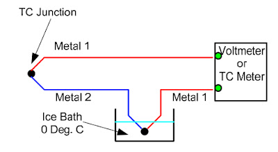
By adding a second series thermocouple suspended in an ice bath, the cold junctions at the meter are of identical metals and cancel each other. In addition, the temperature of the ice bath is known to be 0 Deg. C and becomes the reference end of the thermocouple.

The temperature equation is now simplified and once again becomes:

T = Tjunc – Tref
Theory of Thermocouple Operation
While the ice bath reference junction eliminates errors, it is clearly impractical for most, if not all applications.  Fortunately, all of today’s thermocouple read back options (meters, chart recorders, PLCs, etc.), come equipped with cold junction compensation, usually a thermistor and associated circuitry and software. By taking the cold junction worries out of the picture, the thermocouple remains one of the simplest, most robust and widely used temperature measurement devices around.

Monday, February 25, 2019

Thermocouple Wire Insulation Materials

Thermocouple Wire Insulation

Insulated thermocouple wire is single pair wire that can be made into a thermocouple. Thermocouple wire is available with many types of electrical insulation. The choice of the proper insulation material is based on cost, temperature rating, chemical & UV resistance and wear resistance. Below is a run-down of the most common thermocouple wire insulation materials.

Nylon
  • Suggested operating range: -85°F to 250°F (-65°C to 121°C)
  • Nylon provides high tensile, impact and flexural resistance.  It has excellent resistance to abrasion and is unaffected by most alkalis, oil, grease, dilute mineral acids and most organic acids.  It is inert to most organic solvents including hydraulic fluid and aviation oil. The individual conductors and outer jacket are extruded.
Fluorinated Ethylene Propylene (FEP) 
  • Suggested operating range: -90°F to 400°F (-67°C to 204°C)
  • FEP retains useful strength and flexibility over broad ranges of environmental temperature or thermal aging. FEP is flame retardant and non-propagating in fire conditions. It is moisture and chemical resistant and accepted for use around food and pharmaceuticals. The individual conductors and outer jacket are extruded.
Perfluoroalkoxy (PFA) 
  • Suggested operating range: -328°F to 500°F (-200°C to 260°C)
  • Flame retardant PFA provides flexibility and toughness with stress crack resistance, resistance to weather, non-aging characteristics and a low coefficient of friction.  PFA also provides outstanding electrical characteristics, as well as resistance to virtually all chemicals.  The individual conductors and outer jacket are extruded.
Tetrafluoroethylene (TFE) 
  • Suggested operating range: -328°F to 500°F (-200°C to 260°C)
  • TFE is flame retardant (passes IEEE 383 & VW-1 flame tests) and has excellent solvent and abrasion resistance.  TFE is unaffected by long term exposure to virtually all chemicals and solder iron temperatures. The individual conductors and outer jacket are insulated with TFE Tape.
Polymide Tape (Kapton) 
  • Suggested operating range: -400°F to 600°F (-240°C to 315°C)
  • Kapton is extremely tough.  It has excellent abrasion, impact and cut through resistance, very high resistance to oxidative degradation, weathering, and all chemicals except strong bases.  Kapton also offers high dielectric strength and insulation resistance.  Kapton does not support combustion; even at extremely high temperatures, it decomposes slowly without visible burning.  It is also resistant to radiation. The individual conductors and outer jacket are insulated with Kapton Tape.
Fiberglass 
  • Suggested maximum operating temperature: 900°F (482°C) continuous 1000°F (538°C) single exposure {Impregnation maintained to 400°F (200°C)}
  • Fiberglass insulation, with the special binder impregnation, offers good moisture and chemical resistance, as well as good abrasion resistance.  Typical applications include aerospace, foundries, heat treating, plastics industry and a wide variety of other uses.
  • Hi-Temp Fiberglass - Suggested maximum operating temperature: 1300°F (704°C) continuous, 1600°F (871°C) single exposure {Impregnation maintained to 400°F (200°C)}
For more information about thermocouple wire insulation materials contact Duro-Sense Corporation by calling 310-533-6877 or visiting https://duro-sense.com.

Friday, February 15, 2019

Temperature Sensing IS Rocket Science


Duro-Sense Corporation provides the precision temperature sensors to the aerospace, aviation, and space industries. Duro-Sense engineers bring proven solutions to your most difficult problems. Their R&D department is staffed with some of the industry's most qualified people, working in the most modern facilities to help advance the state of the art in temperature measurement.