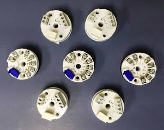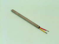
In an industrial plant, where there are normally long distances between the measuring points and the receiving instrumentation, some important aspects regarding the location of the transmitters can be mentioned.
There are basically three different locations for the mounting of the temperature transmitters:
- In-head mounting - inside the connection head of the temperature sensors.
- Field mounting – close to the temperature sensors.
- Central mounting - in the vicinity of the control room
In-head mounting
The transmitters are mounted directly inside the connection head and are normally replacing the terminal block. This way of mounting normally offers the biggest advantages. It is however necessary to be aware of the environmental influence (mainly the temperature) on the measurement accuracy.
Advantages
- Maximum safety in the signal transmission. The amplified signal, e.g. 4- 20 mA, is very insensitive to electrical disturbances being induced along the transmission cable.
- Cost savings for the transmission cables. Only two leads are required if a 2- wire transmitter is used.
- Cost savings for installation. No extra connection points because of the transmitter.
- Cost and space savings. No extra housings or cubicles are needed.
- Field instruments, e.g. indicators, can easily be installed, also at a later stage without redesigning the measuring circuits.
Disadvantages
- The ambient temperatures can be out- side the allowed limits for the transmitters.
- The ambient temperature influence on the measuring accuracy has to be considered.
- Extreme vibrations might cause malfunction of the transmitters.
- The location of the temperature sensor can give maintenance problems.
Field mounting
The transmitters are either mounted directly beside the temperature sensors or in the vicinity of the sensors. Often more than one transmitter is mounted in the same field box.
This method is more expensive than In-head mounting, but otherwise a good alternative offering most of the advantages of In-head mounting without the disadvantages mentioned above.
Advantages
- High safety in the signal transmission. The main part of the signal transmission is made with an amplified signal.
- No extreme temperatures or vibrations exist. This facilitates accurate and safe measurements.
- Cost savings for transmission cables.
- A wider selection of transmitters is available. DIN rail transmitters can also be used.Field instruments can often be installed easily.
- Maintenance can normally be carried out without problems.
Disadvantages
- Higher installation costs compared to In-head mounting.
- Costs and space requirements for transmitter boxes or cubicles.
Central mounting
In this case, the transmitters are placed in the vicinity of the control room or in another central part of the plant They are often mounted inside cubicles, and/or closed rooms. The ambient conditions are normally very good and stable.
This method offers the most convenient conditions for maintenance and the best possible environment for the transmitters. There are on the other hand some disadvantages that should be considered.
Advantages
- Convenient conditions for installation, commissioning and maintenance.
- Minimum risk for environmental influences (e.g. temperature influence).
Disadvantages
- Reduced safety in the signal transmission. The low-level sensor signal is rather sensitive to electrical disturbances being induced along the trans- mission cable.
- Relatively high costs for cabling. T/C measurements require compensation or extension cables all the way to the transmitters. RTD measurements with high accuracy should be done in 4-wire connection to get rid of the lead resistance influence.
- Costs and space requirements for cubicles or frames.
- Rather complicated and expensive to connect field instruments, e.g. indicators.
For more information on using temperature transmitters, contact
Duro-Sense by calling 310-533-6877 or by visiting
https://duro-sense.com.


