Sunday, March 31, 2019

Digital Food Thermometers: Thermocouples

Digital Food Thermometers
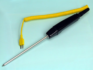
Specialized thermocouple, with handle and sharpened point,
 used in food preparation.
Of all food thermometers, thermocouple thermometers reach and display the final temperature the fastest - within 2 to 5 seconds. The temperature is indicated on a digital display.

A thermocouple measures temperature at the junction of two fine wires located in the tip of the probe. Thermocouples used in scientific laboratories have very thin probes, similar to hypodermic needles, while others may have a thickness of 1/16 of an inch.

Since thermocouple thermometers respond so rapidly, the temperature can be quickly checked in a number of locations to ensure that the food is safely cooked. This is especially useful for cooking large foods, such as roasts or turkeys, when checking the temperature in more than one place is advised. The thin probe of the thermocouple also enables it to accurately read the temperature of thin foods such as hamburger patties, pork chops, and chicken breasts.

Thermocouples are not designed to remain in the food while it's cooking. They should be used near the end of the estimated cooking time to check for final cooking temperatures. To prevent overcooking, check the temperature before the food is expected to finish cooking.

Thermocouples can be calibrated for accuracy.

For more information of food industry thermocouples, contact Duro-Sense Corporation by calling 310-533-6877 or visiting https://duro-sense.com.
Monday, March 25, 2019

A Pro and Con Comparison of Thermocouples and RTDs


Thermocouple Advantages 
  • Inexpensive
  • Wide temperature range
  • Various types, sizes and application methods
  • Remote read back
  • Read back electronics can be simple
  • Usable in virtually any environment
Thermocouple Disadvantages
  • Requires cold junction compensation
  • Slow response time
  • Not as accurate as many other devices without good CJC and calibration
  • Susceptible to noise
  • Connection cable/wire is expensive compared to copper conductors
  • Cable/wire length is limited
RTD Advantages
  • More linear than thermocouples
  • Cold junction not an issue
  • Special cable/wire not needed
  • Cable/wire length can be much longer than TC’s
  • Better noise immunity
  • More stable over time than thermocouples
  • Remote read back
  • Usable in virtually any environment
RTD Disadvantages
  • More expensive than thermocouples
  • More delicate than thermocouples unless encased
  • Not as wide of temperature range as thermocouples
  • Requires more conductors per device
  • Read back electronics more complex

Tuesday, March 12, 2019

Theory of RTD Operation

Theory of RTD OperationAn RTD is a temperature measuring device that changes resistance with temperature change, rather than changing voltage, as with a thermocouple.

Most commonly used is the platinum 100 ohm RTD because of their stability in air and linearity. Their resistance is 100 ohms @ 0 Deg.C and increases with temperature.

Theory of RTD OperationCommon terms associated with RTD’s are temperature coefficient or alpha, and tolerance class.

Alpha is ohms per ohm per Deg.C.
The average resistance change per unit of temperature from boiling point to ice point of water:

  • Rboiling – Rice point/100deg/100ohms
  • 138.5 – 100.0/100/100 = .00385


Tolerance class is the amount an RTD will differ from the standard resistance curve per Deg.C.

  • Class A (+/- .15 + .002*t)
  • @ temp of 100DegC = +/- .35DegC

When ordering an RTD, a tolerance class will be part of the order, dependent on the application. IEC 751 stipulates that the RTD be marked with their nominal R0 value, their tolerance class, the wiring configuration and the temperature range.
Theory of RTD Operation
3-wire configuration

  • Pt100 / A / 3 / -100/+200  = Platinum 100 Ohm / Class A / 3-Wire / -100 to +200 Deg.C
The most common RTD configuration is the 3-wire type. This configuration is more than adequate for 99.9% of applications. If absolute accuracy is needed, a fourth wire can be introduced, but rarely is it worth the added cost.
Theory of RTD Operation
2-wire configuration

Another configuration is a two wire RTD with a stand-alone loop. (Probably rarely used today).

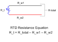
Since the RTD is a resistance device, the resistance of the wires used to connect the RTD to the measurement meter introduces errors and must be known. This is the reason a third (or fourth), wire is used.

Theory of RTD Operation
3rd wire used to cancel wire error
First the meter reads the resistance of the two common wires to determine the value of Rwire. For a three wire RTD, it is assumed that this resistance is the same as that of one common and one non-common wire.

Then the meter reads the resistance of one of the common wires, the RTD, and the non-common wire to determine Rtotal

Theory of RTD Operation
Meter reading 2 common wires
Meter electronics and software then subtract Rwire from Rtotal to get Rt which is then converted to a temperature.


Theory of RTD Operation


Rt = Rtotal – Rwire