Monday, January 28, 2019

Where to Mount Industrial Temperature Transmitters?

Temperature TransmittersIn an industrial plant, where there are normally long distances between the measuring points and the receiving instrumentation, some important aspects regarding the location of the transmitters can be mentioned.

There are basically three different locations for the mounting of the temperature transmitters:

  • In-head mounting - inside the connection head of the temperature sensors.
  • Field mounting – close to the temperature sensors.
  • Central mounting - in the vicinity of the control room

In-head mounting

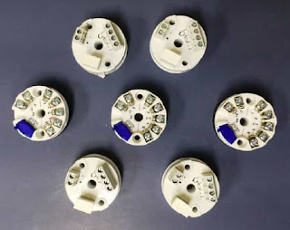
The transmitters are mounted directly inside the connection head and are normally replacing the terminal block.  This way of mounting normally offers the biggest advantages. It is however necessary to be aware of the environmental influence (mainly the temperature) on the measurement accuracy.

Advantages
  • Maximum safety in the signal transmission. The amplified signal, e.g. 4- 20 mA, is very insensitive to electrical disturbances being induced along the transmission cable.
  • Cost savings for the transmission cables. Only two leads are required if a 2- wire transmitter is used.
  • Cost savings for installation. No extra connection points because of the transmitter.
  • Cost and space savings. No extra housings or cubicles are needed.
  • Field instruments, e.g. indicators, can easily be installed, also at a later stage without redesigning the measuring circuits.
Disadvantages
  • The ambient temperatures can be out- side the allowed limits for the transmitters.
  • The ambient temperature influence on the measuring accuracy has to be considered. 
  • Extreme vibrations might cause malfunction of the transmitters.
  • The location of the temperature sensor can give maintenance problems.

Field mounting

The transmitters are either mounted directly beside the temperature sensors or in the vicinity of the sensors. Often more than one transmitter is mounted in the same field box.

This method is more expensive than In-head mounting, but otherwise a good alternative offering most of the advantages of In-head mounting without the disadvantages mentioned above.

Advantages
  • High safety in the signal transmission. The main part of the signal transmission is made with an amplified signal.
  • No extreme temperatures or vibrations exist. This facilitates accurate and safe measurements.
  • Cost savings for transmission cables.
  • A wider selection of transmitters is available. DIN rail transmitters can also be used.Field instruments can often be installed easily.
  • Maintenance can normally be carried out without problems.
Disadvantages
  • Higher installation costs compared to In-head mounting.
  • Costs and space requirements for transmitter boxes or cubicles.

Central mounting

In this case, the transmitters are placed in the vicinity of the control room or in another central part of the plant They are often mounted inside cubicles, and/or closed rooms. The ambient conditions are normally very good and stable.

This method offers the most convenient conditions for maintenance and the best possible environment for the transmitters. There are on the other hand some disadvantages that should be considered.

Advantages
  • Convenient conditions for installation, commissioning and maintenance.
  • Minimum risk for environmental influences (e.g. temperature influence).
Disadvantages
  • Reduced safety in the signal transmission. The low-level sensor signal is rather sensitive to electrical disturbances being induced along the trans- mission cable.
  • Relatively high costs for cabling. T/C measurements require compensation or extension cables all the way to the transmitters. RTD measurements with high accuracy should be done in 4-wire connection to get rid of the lead resistance influence.
  • Costs and space requirements for cubicles or frames.
  • Rather complicated and expensive to connect field instruments, e.g. indicators.

For more information on using temperature transmitters, contact Duro-Sense by calling 310-533-6877 or by visiting https://duro-sense.com.

Sunday, December 30, 2018

Wednesday, December 12, 2018

Happy Holidays from Duro-Sense!

From all of us at Duro-Sense, we wish our customers, partners and vendors a safe and happy holiday season and a wonderful 2019!


Monday, December 10, 2018

Duro-Sense a Critical Partner in Hydrogen Contamination Detector

We take for granted the gasoline (or diesel) we put in our cars and trucks is free from contaminants when pumped in to our gas tanks. The purity we've come to expect at the fuel pump didn't happen overnight. It took many years, and thousands of engineering hours, to develop the refining processes that produces today's clean gasoline and diesel. 

Fuel Cell Vehicles are a category of electric vehicle (EV's). Fuel cell vehicles use hydrogen gas (H2) to power an electric motor. Unlike conventional vehicles which run on gasoline or diesel, fuel cell cars and trucks combine hydrogen and oxygen to produce electricity to drive the motor. 

Similar to the path that gasoline and diesel processing took toward purity, the use of H2 as feedstock for fuel cells in transportation has driven requirements for H2 purity standards to very strict levels. This push has also elevated the need for cost-effective and reliable instruments that can sample H2 near the nozzle of a delivery pump, and either certify acceptability or provide a signal to shut off the fuel distribution system.

Duro-Sense Corporation, a California based manufacturer of high quality temperature sensors, is part of a team working under a DOE funded research program to develop a Hydrogen Contamination Detector. The sensor, which will be installed at hydrogen fueling stations, will detect poor quality hydrogen gas before entering the fuel cell vehicle. The sensor is intended to detect multiple impurities at extremely low levels in hydrogen to prevent fuel cell performance degradation. 

Duro-Sense is designated as the industrial partner and vendor aiding in defining the commercial manufacturability of the Hydrogen Contamination Detector. 

As part of their preliminary work, a thermocouple embodiment was selected as a cost-effective platform for the Hydrogen Contamination Detector because:
  • Direct Commercial Availability
  • Proven History of Reliability and Robustness
  • Adaptability of Conductor Materials for Most
  • Appropriate Catalyst for Each Contaminant
  • Ability to Incorporate up to 12 Conductors a Single Thermocouple, Reducing Fluid Stream Penetrations
They also assisted with a high pressure pass-through to integrate the sensor into fluid stream to accommodate a pressure rating of 30,000 PSI using a cone and thread style fluid connection.

The Hydrogen Contamination Detector project is still in its very early stages, and research and development continues, subject to funding and continued interest in alternative fuel technology.

For more information, contact Duro-Sense at 310-533-6877 of visit their web site at https://duro-sense.com.

Tuesday, December 4, 2018

3 Bottom Line Criteria to Help You Choose Between Thermocouples and RTDs

Temperature Sensor Selection Criteria
Both RTD and thermocouple probes monitor temperature but which one is right for your application?

The first question to ask yourself is what is the temperature range you are trying to monitor?
Generally, if the temperature is above a hundred and fifty degrees Celsius, a thermocouple would be used. For anything below a hundred and fifty degrees Celsius, an RTD would be used.

The next question to ask is what is the required sensor accuracy? 
RTDs provide more accurate readings with repeatable results, this is why RTDs are typically used when temperatures are within its monitoring range.

The last question is what is the purchase budget and how many do you need?
Thermocouples can be up to three times less expensive than RTD probes making thermocouples a good choice when purchasing a large quantity or when the budget is tight

These three criteria are VERY basic, and intended just to point you in the right direction. There are many other differences between thermocouples and RTDs that need to be understood before application.  Always consult a temperature sensor application expert prior to installing or specifying a thermocouple or RTD where failure can cause harm.

Duro-Sense Corporation
https://duro-sense.com
(310) 533-6877

Wednesday, November 28, 2018

Best Practice for Mounting Thermocouples in Pipes

not recommended
Diagram 1 - Not recommended.
Immersion type thermocouples are used to measure the temperature of liquid flowing in a pipe or sitting in a vessel. The particular orientation for any installation depends on the application, whether additional hardware is required, and the relative dimensions of the thermocouple sheath and the pipe.

There are however, recommended practices for placing thermocouples in the piping flow stream.

As you can see from diagram 1, placing the thermocouple in a tee, positioned perpendicular to flow is not recommended. This is because the conduction along the sensing area may be non-negligible and could bias the measurement, depending on the liquid and ambient temperatures. In addition it may be hard to know precisely where the measurement junction is located along the cross section of the pipe in this configuration.

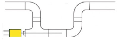
Ideally they should be mounted in a tee where an elbow would normally be used as you see in diagram 2. If possible the thermocouple should be oriented along the normal flow direction, and the measurement located downstream of the T-bend (the T will help mix the liquid if it is not thermally uniform).
recommended
Diagram 2 - Recommended orientation.
If there is no convenient spot where an elbow would normally be used, a u-shape can be adapted to allow the installation for the tee. See diagram 3.

U shape
Diagram 3 - Use U shape if there is no convenient placement for a tee.
For more information, contact Duro-Sense by calling 310-533-6877 or visit their web site at https://duro-sense.com.