Wednesday, May 16, 2018

RTD and Thermocouple Selection and Location for Optimal Control

Loop diagram
Loop diagram *
A perfectly designed temperature loop would precisely balance the power required to heat the media to it's desired temperature while compensating for system losses. In the real world however, there are many external variables that upset the balance between energy input and desired temperature. To offset these external variables and ensure adequate power is available to do the work, energy calculations with liberal safety factors are coupled with temperature controllers that throttle or proportion the amount of energy added to the process.

Most temperature control loops have (5) four major components:

1) The media to be heated (e.g. metal platen, a tank of liquid, a stream of gas)
2) A energy source (e.g. electric heater, steam, hot oil, flame)
3) A temperature sensor (thermocouple, RTD)
4) A controller (e.g. electronic thermostat, PID controller)
5) Control element (e.g. control valve, SCR, SSR)

Temperature controllers provide sophisticated functions that "learn" or understand the relationship between available power and sensor temperature. They then adjust the amount of energy (heat) added, based on the current reading of the sensor and the desired temperature setpoint.  Unfortunately, temperature controllers are often relied upon to overcome the oversights and inadequacies of poor control loop design.

Lag time
Lag time *
In poor control situations the controller usually takes the blame, when in actuality,  the problem lies in the system design. The controller's actions are a function of the difference between setpoint and sensor reading, the availability of energy to eliminate that error, and the sensor lag time. The further the sensor or energy source is located from the process media, the wider the swings in energy input will be, and therefore produce a more difficult loop to balance. Considering this, it is important to optimize the sensor (thermocouple or RTD) placement. Any distance or barrier between sensor and process media introduces lag which is an impediment to close control.

In the most ideal situation, temperature sensors, the energy source and process media would all be at the same physical location. Since it's virtually impossible to accomplish this, compromises have to be made to allow for the mechanical, physical, and electrical realities of the application. Here are some practical recommendations for sensor selection and placement to improve temperature loop performance:
  • Thermocouples, because of their low mass generally have a response advantage over RTDs.
  • Exposed junction thermocouples are the fastest responding (least lag) sensor choice, but they are also the most prone to physical and chemical damage.
  • Narrow, sheathed, grounded junction magnesium oxide insulated thermocouples are nearly as fast as exposed junctions, and provide protection from the process media.
  • Applications that require protection sheaths and thermowells for RTDs and thermocouples increase sensor lag time.
  • An immersion length of at least 10 times the diameter of the thermowell or sensor sheath should be used to minimize heat loss along the sensor sheath or thermowell wall from tip to process connection.
  • Where possible, insert the temperature sensor in a pipe elbow into the oncoming flow.
  • Tapered, swaged, or stepped thermowells are  faster responding
  • Always make sure the fit between sensor outer diameter and thermowell inner diameter is tight, and that the tip of the sensor is in direct contact with the thermowell. 

* Images courtesy of Tony Kuphaldt and his book "Lessons In Industrial Instrumentation"

Thursday, May 3, 2018

Advantages and Disadvantages of Thermocouples

Industrial thermocouples
Industrial thermocouples in ceramic
protection tubes (Duro-Sense)
Temperature sensors, inherent to their design or operating principle, are often the weakest link in the control loop. Fragility, noise sensitivity, and material deterioration have to be considered when applying temperature sensors. Generally speaking, when it comes to temperature sensing technology, RTDs are more accurate and stable, but are also fragile; thermistors have greater temperature sensitivity, but their electrical properties can change overtime; thermocouples (TC) are rugged, inexpensive, and operate over a wide temperature range, but they do have drawbacks that need to be understood for successful implementation.

The thermocouple's primary disadvantage is their weak output signal and their susceptibility to electrical noise. The mV signal generated is so small it requires conditioning, namely amplification and linearization.  The good news is this conditioning is built-in to and provided by the TC's corresponding controller, indicator or transmitter.  Calibration drift due to oxidation, contamination, or other physical changes to the alloys is another problem associated with thermocouples, requiring a facility to implement periodic recalibration procedures. Lastly, thermocouples require alloy-matching thermocouple extension wire when running lead wires any distance from sensor to instrument. This adds cost, as thermocouple extension wire is more expensive than standard wire.

Despite these concerns, thermocouples are widely used in industry because of their relative low cost, ruggedness, wide selection of operating ranges, and versatility in size, shape, and configuration. They have been used in millions of process control applications for over a generation, and provide an excellent balance of performance, cost, and simplicity. Successful application depends on knowing thermocouple's strengths and weaknesses, and consulting with an applications expert prior to specifying or installing any temperature sensor is always recommended to ensure the sensor's longest life and best performance.

Friday, April 27, 2018

Thermocouple Junction Configurations

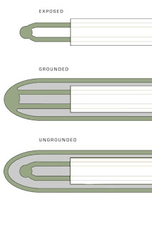
Thermocouple JunctionThermocouples are simple devices made up of several key components: thermocouple wire, electrical
insulation, and the a welded wire sensing junction. Many thermocouple designs also include a stainless steel sheath that protects the thermocouple from vibration, shock, and corrosion.

A thermocouple has three variations of sensing tip (or junction):
  1. Exposed junction, where the exposed wire tips and welded bead have no covering or protection.
  2. Grounded junction, where the welded bead is in physical contact with the thermocouple's sheath.
  3. Ungrounded junction, where the tip is inside the thermocouple sheath, but is electrical (and somewhat thermally) insulated from the sheath (no sheath contact).
Exposed junction thermocouples respond to temperature change quickly and are less costly, but their signals are susceptible erratic reading caused by induced or conducted electrical noise. Because there is no sheath, they are also prone to mechanical damage and ambient contamination.

Grounded junction thermocouples provide fast response and are mechanically more robust, with a metallic sheath that protects the thermocouple both mechanically and from contaminants. But because their sensing tip is in contact with the external sheath, their signal still can be affected by externally induced or conducted electrical noise.

Ungrounded thermocouples, like grounded, are protected mechanically and from ambient contaminants by their sheath. However, their sensing junctions are kept separate from their metallic sheath, isolating the junction from external electrical  interference. This separation does come at a small cost in temperature sensing responsiveness though.

For safety, precision, and optimum performance, always talk to an applications specialist when applying temperature sensors. A short phone call can prevent major headaches and lost time in  troubleshooting a misapplied thermocouple.

Saturday, April 14, 2018

Thermocouples and RTDs Used in Power Plants

Thermocouple and RTD Used in Power Plants
The majority of temperature measuring in a electrical generating plant are done with RTDs (resistance temperature detectors) and thermocouples (T/Cs).

RTD's are devices that produce a measurable resistance change with temperature change, while thermocouples produce a mV signal change in response to temperature change.

RTD's are constructed of a a thin conductor (nickel, platinum, copper) wrapped around a glass or ceramic bobbin, inserted into a protective sheath, and backfilled with an electrically inert, but thermally conductive, material.

Power plants historically use 100-ohm platinum, 100-ohm nickel, 120-ohm nickel, and 10-ohm copper RTDs. While providing excellent accuracy and long term stability, RTDs are prone to mechanical shock and vibration found in a generating facility. They are more expensive than thermocouples and application temperatures are generally limited to around up to 1110°F. One very attractive feature for RTDs are their inherent electrical noise immunity, a significant advantage over thermocouples. Finally, common, inexpensive instrument wire is used for connecting the RTD to the measuring instrumentation.

A thermocouple consists of two wires, made of dissimilar alloys, joined together at each end. One junction is designated the hot junction, the other junction is designated as the cold (or reference junction). When the hot junction experiences a change in temperature, a voltage is generated that is proportional to the difference in temperature between the hot and cold junctions. 

T/Cs are be made of different combinations of alloys and "calibrations" for use at various temperature ranges. The most common thermocouples for the power generation industry applications under 1800 °F are type are J, K and N ; for applications over 1800 °F,  types R and S are common. Aside from the obvious higher temperature capability, thermocouples provide faster response and greater shock and vibration endurance. However, thermocouples, due to the minuter signals the produce, are more susceptible to conducted and radiated electrical noise.  Another concern with thermocouples are their degradation over time when used at elevated temperatures and are therefore less stable than RTDs. One final issue is the need to run costly thermocouple extension wire of the same type as the thermocouple between sensor and measuring instrument.

When in doubt about which sensor is best to apply in a power plant application, contact an application expert who will help you choose the ideal sensor for your requirements.

https://duro-sense.com
Ph: 310-533-6877


Tuesday, April 3, 2018

What are Plastics Thermocouples?

Plastics Thermocouple
Right Angle, Bayonet Style, Plastics Thermocouples
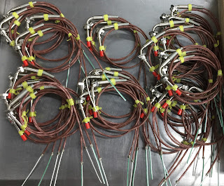
The term "plastics thermocouple" refers to a style of thermocouple designed and used by the plastics, packaging and rubber industries.  They are installed on injection molding, thermoforming, vacuum forming, and extruding equipment to accurately sense the temperature of the plastic molds and nozzles. While there are a variety of configurations of plastics thermocouples - such as bayonet, washer style, shim style, nozzle, and right angle - their basic components remains the same.

In most cases, plastics thermocouples are ANSI type J or type K calibration. Type J or K lead wire is available in a variety of insulation materials and protection options, such as high temperature fiberglass, PVC, stainless steel braided fiberglass, or stainless steel flexible armor cable. Electrical connections are most commonly bare leads, male thermocouple jacks, female thermocouple plugs, or spade lugs.

Bayonet designs are straight or right angle, and use industry standard bayonet fittings that easily retrofit most injection molding and plastics processing equipment. These fittings allow for adjustable depth and are spring loaded for maintaining goos contact with the media. Washer and shim style thermocouples weld or crimp the thermocouple sensing junction right to the washer or shim.

Bayonet thermocouples use a tube and wire design utilizing stranded thermocouple cable through out the probe. The metallic probe is made of 301, 304 or 316 series stainless steel. The thermocouple can made with a grounded, or ungrounded junction. A grounded junction is welded to the tip of the probe and, while it has very fast response, it can conduct electrical noise back to the instrumentation. An ungrounded junction is isolated from the metallic probe, and prevents electrical noise transmission. However, ungrounded junctions are slightly slower to respond to temperature changes.

For more information on plastics thermocouples, contact Duro-Sense by visiting https://duro-sense or by calling 310-533-6877.

Thursday, March 29, 2018

High Quality, Precision Temperature Sensors for Military and Aerospace Applications

Duro-Sense offers a wide selection of thermocouples and RTD's for the military and aerospace industries. All sensors are designed for high-reliability and to endure shock,
vibration, and widely-changing ambient environments. All products are calibrated to NIST standards and are ISO9001, AS9100, ISO17025 compliant. All temperature sensors are designed and tested to provide exceptional accuracy, stability and reliability in the most demanding environments.

Call 310-533-6877 of visit https://duro-sense.com for more information.


Monday, March 26, 2018

The 3 Most Common Temperature Sensors: Thermocouples, RTD's and Thermistors

This post explains the basic operation of the three most common temperature sensing elements - thermocouples, RTD's and thermistors.

Thermocouple
Thermocouple (image courtesy of Duro-Sense)
A thermocouple is a temperature sensor that produces a micro-voltage from a phenomena called the Seebeck Effect. In simple terms, when the junction of two different (dissimilar) metals varies in temperature from a second junction (called the reference junction), a voltage is produced. When the reference junction temperature is known and maintained, the voltage produced by the sensing junction can be measured and directly applied to the change in the sensing junctions' temperature.

Thermocouples are widely used for industrial and commercial temperate control because they are inexpensive, fairly accurate, have a fairly linear temperature-to-signal output curve, come in many “types” (different metal alloys) for many different temperature ranges, and are easily interchangeable. They require no external power to work and can be used in continuous temperature measurement applications from -185 Deg. Celsius (Type T) up to 1700 Deg. Celsius (Type B).

Common application for thermocouples are industrial processes, the plastics industry, kilns, boilers, steel making, power generation, gas turbine exhaust and diesel engines, They also have many consumer uses such as temperature sensors in thermostats and flame sensors, and for consumer cooking and heating equipment.

resistance temperature detectors
Wire-wound RTD (image courtesy of Wikipedia)
RTD’s (resistance temperature detectors), are temperature sensors that measure a change in resistance as the temperature of the RTD changes. They are normally designed as a fine wire coiled around a bobbin (made of glass or ceramic), and inserted into a protective sheath. The can also be manufactured as a thin-film element with the pure metal deposited on a ceramic base much like a circuit on a circuit board.

The RTD wire is usually a pure metal such as platinum, nickel or copper because these metals have a predictable change in resistance as the temperature changes. RTD’s offer considerably higher accuracy and repeatability than thermocouples and can be used up to 600 Deg. Celsius. They are most often used in biomedical applications, semiconductor processing and industrial applications where accuracy is important. Because they are made of pure metals, they tend to more costly than thermocouples. RTD’s do need to be supplied an excitation voltage from the control circuitry as well.

Thermistor
Thermistor (image courtesy of Wikipedia)
The third most common temperature sensor is the thermistor. Thermistors work similarly to RTD’s in that they are a resistance measuring device, but instead of using pure metal, thermistors use a very inexpensive polymer or ceramic material as the element. The practical application difference between thermistors and RTD’s is the resistance curve of thermistors is very non-linear, making them useful only over a narrow temperature range.

Thermistors however are very inexpensive and have a very fast response. They also come in two varieties, positive temperature coefficient (PTC - resistance increases with increasing temperature), and negative temperature coefficient (NTC - resistance decreases with increasing temperature). Thermistors are used widely in monitoring temperature of circuit boards, digital thermostats, food processing, and consumer appliances.

For more information, contact Duro-Sense by calling 310-533-6877 or visit https://duro-sense.com.