Wednesday, November 28, 2018

Best Practice for Mounting Thermocouples in Pipes

not recommended
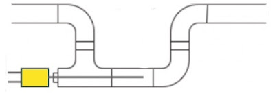
Diagram 1 - Not recommended.
Immersion type thermocouples are used to measure the temperature of liquid flowing in a pipe or sitting in a vessel. The particular orientation for any installation depends on the application, whether additional hardware is required, and the relative dimensions of the thermocouple sheath and the pipe.

There are however, recommended practices for placing thermocouples in the piping flow stream.

As you can see from diagram 1, placing the thermocouple in a tee, positioned perpendicular to flow is not recommended. This is because the conduction along the sensing area may be non-negligible and could bias the measurement, depending on the liquid and ambient temperatures. In addition it may be hard to know precisely where the measurement junction is located along the cross section of the pipe in this configuration.

Ideally they should be mounted in a tee where an elbow would normally be used as you see in diagram 2. If possible the thermocouple should be oriented along the normal flow direction, and the measurement located downstream of the T-bend (the T will help mix the liquid if it is not thermally uniform).
recommended
Diagram 2 - Recommended orientation.
If there is no convenient spot where an elbow would normally be used, a u-shape can be adapted to allow the installation for the tee. See diagram 3.

U shape
Diagram 3 - Use U shape if there is no convenient placement for a tee.
For more information, contact Duro-Sense by calling 310-533-6877 or visit their web site at https://duro-sense.com.

Monday, November 12, 2018

Friday, November 9, 2018

Platinum Resistance Temperature Detectors

Platinum Resistance Thermometers Detectors (RTDs) rely on the fact that platinum, like many other metals, exhibits increased electrical resistance as temperature rises. For example, a conventional RTD designed to provide 100 Ohms at 0 °C has a resistance in the neighborhood of 80 Ohms at -50 °C and 120 Ohms at 50 °C, or a sensitivity of about 0.4 Ohms per degree. RTDs constructed to particularly exacting specifications, termed Standard Platinum Resistance Thermometers, are named as the defining measurement tools for interpolating temperatures under ITS-90. In general, RTDs can have high accuracy (0.01 °C), stability, and repeatability across a wide range of temperatures from -200 °C to 500 °C.

Typically the platinum element is formed into thick or thin films, or the platinum wire is arranged in two, three or four helical coils (see diagram, right) – the more coils, the higher the sensitivity. The film or wire is placed inside a glass or ceramic enclosure, and can be supported by loose or compacted MgO. Platinum-based leads connect the probe unit to the thermometer electronics, which convert the electrical signal to temperature.

RTDs are broadly divided into two groups: Industrial RTDs and Standard Platinum Resistance Thermometers, depending on sensitivity and robustness. ASTM and IEC define several classes of RTDs, each with a different set of specifications. An ASTM "Class A" unit, for example, has an out-of-the-box tolerance — maximum permissible error — that ranges from 0.47 °C at -200 °C to 0.13 °C at 0 °C to 0.98 °C at 500 °C.

Advantages

  • Wide temperature range
  • Resistance-temperature relationship is well characterized.
  • Rugged construction in industrial RTDs
  • Available in different shapes and sizes – application specific
  • Can be used with a digital temperature read-out device.

Disadvantages

  • Mechanical shock and vibration will cause drift.
  • Deterioration at elevated temperatures (e.g., >500 °C)
  • 2-and 3-wire devices need lead-wire compensation.
  • Non-hermetically sealed RTDs will deteriorate in environments with excessive moisture.


Post abstracted from "Mercury Thermometer Alternatives: Platinum Resistance Thermometers (PRTs)" by NIST.

Wednesday, October 31, 2018

Thermocouple Extension Wire

In every thermocouple circuit there must be both a measurement junction and a reference junction: this is an inevitable consequence of forming a complete circuit (loop) using dissimilar-metal wires. As we already know, the voltage received by the measuring instrument from a thermocouple will be the difference between the voltages produced by the measurement and reference junctions.

Since the purpose of most temperature instruments is to accurately measure temperature at a specific location, the effects of the reference junction’s voltage must be “compensated” for by some means, either a special circuit designed to add an additional canceling voltage or by a software algorithm to digitally cancel the reference junction’s effect.

In order for reference junction compensation to be effective, the compensation mechanism must “know” the temperature of the reference junction. This fact is so obvious, it hardly requires mentioning. However, what is not so obvious is how easily this compensation may be unintentionally defeated simply by installing a different type of wire in a thermocouple circuit.

To illustrate, let us examine a simple type K thermocouple installation, where the thermocouple connects directly to a panel-mounted temperature indicator by long wires:


Like all modern thermocouple instruments, the panel-mounted indicator contains its own internal reference junction compensation, so that it is able to compensate for the temperature of the reference junction formed at its connection terminals, where the internal (copper) wires of the indicator join to the chromel and alumel wires of the thermocouple. The indicator senses this junction temperature using a small thermistor thermally bonded to the connection terminals.

Now let us consider the same thermocouple installation with a length of copper cable (two wires) joining the field-mounted thermocouple to the panel-mounted indicator:


Even though nothing has changed in the thermocouple circuit except for the type of wires joining the thermocouple to the indicator, the reference junction has completely shifted position. What used to be a reference junction (at the indicator’s terminals) is no longer, because now we have copper wires joining to copper wires. Where there is no dissimilarity of metals, there can be no thermoelectric potential. At the thermocouple’s connection “head,” however we now have a joining of chromel and alumel wires to copper wires, thus forming a reference junction in a new location at the thermocouple head. What is worse, this new location is likely to be at a different temperature than the panel-mounted indicator, which means the indicator’s reference junction compensation will be compensating for the wrong temperature.

The only practical way to avoid this problem is to keep the reference junction where it belongs: at the terminals of the panel-mounted instrument where the ambient temperature is measured and the reference junction’s effects accurately compensated. If we must install “extension” wire to join a thermocouple to a remotely-located instrument, that wire must be of a type that does not form another dissimilar-metal junction at the thermocouple head, but will form one at the receiving instrument.

An obvious approach is to simply use thermocouple wire of the same type as the installed thermocouple to join the thermocouple to the indicator. For our hypothetical type K thermocouple, this means a type K cable installed between the thermocouple head and the panel-mounted indicator:


With chromel joining to chromel and alumel joining to alumel at the head, no dissimilar-metal junctions are created at the thermocouple. However, with chromel and alumel joining to copper at the indicator (again), the reference junction has been relocated to its rightful place. This means the thermocouple head’s temperature will have no effect on the performance of this measurement system, and the indicator will be able to properly compensate for any ambient temperature changes at the panel as it was designed to do. The only problem with this approach is the potential expense of thermocouple-grade cable. This is especially true with some types of thermocouples, where the metals used are somewhat exotic (e.g. types R, S, and B).

A more economical alternative, however, is to use something called extension-grade wire to make the connection between the thermocouple and the receiving instrument. “Extension-grade” thermocouple wire is made less expensive than full “thermocouple-grade” wire by choosing metal alloys similar in thermo-electrical characteristics to the real thermocouple wires within modest temperature ranges. So long as the temperatures at the thermocouple head and receiving instrument terminals don’t get too hot or too cold, the extension wire metals joining to the thermocouple wires and joining to the instrument’s copper wires need not be precisely identical to the true thermocouple wire alloys. This allows for a wider selection of metal types, some of which are substantially less expensive than the measurement-grade thermocouple alloys. Also, extension-grade wire may use insulation with a narrower temperature rating than thermocouple-grade wire, reducing cost even further.

Extension-grade cable is denoted by a letter “X” following the thermocouple letter. For our hypothetical type K thermocouple system, this would mean type “KX” extension cable:


Thermocouple extension cable also differs from thermocouple-grade (measurement) cable in the coloring of its outer jacket. Whereas thermocouple-grade cable is typically brown in exterior color, extension-grade cable is usually colored to match the thermocouple plug (yellow for type K, black for type J, blue for type T, etc.)

For more information on thermocouple extension wire, contact Duro-Sense by visiting https://duro-sense.com or by calling 310-533-6877


Reprinted from "Lessons In Industrial Instrumentation" by Tony R. Kuphaldt – under the terms and conditions of the Creative Commons Attribution 4.0 International Public License.


Wednesday, October 24, 2018

The MgO Thermocouple

Magnesium oxide
Magnesium oxide
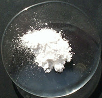
Magnesium oxide (MgO), or magnesia, is a white hygroscopic solid mineral that occurs naturally. The use of compacted magnesium oxide for electrical insulation in wiring cables, heating cables, tubular heating elements, and thermocouples is well known.

While magnesium oxide is the favored high temperature insulating material, many others have been tested. Some examples are aluminum oxide, crystalline silica, and beryllium oxide. For various reasons, ranging from cost, inferior mechanical, poor electrical, and safety issues, magnesium oxide outperforms other powders in industrial applications.

MgO cable
MgO cable cutaway
The MgO thermocouple is constructed by encasing a thermocouple element inside a metal sheath, surrounded by magnesium oxide (MgO). Sheath materials are typically 304 stainless steel, 316 stainless steel, Inconel 600, and 310 stainless steel. The metal sheath is then swaged or drawn down to reduce its diameter. During the drawing process, the powder undergoes considerable compaction, and reaches a compressed density of 70-80% of the crystal density. Despite this change in density, the thermocouples remain very flexible after annealing. Impressively, an MgO thermocouples minimum bend diameter is equal to two times the outside diameter.

MgO thermocouple
MgO thermocouple
MgO thermocouples are available in a variety of sensing junctions. Grounded junctions use a thermocouple welded to the sheath and provides fast response, with good thermocouple protection. Ungrounded (isolated) junctions are insulated from sheath with magnesium oxide and are used to prevent electrical interference from affecting the signal and response is slightly slower than grounded junctions. Exposed junctions are not protected by welded end-cap, provide very quick response, but are susceptible to corrosive media. Dual element common junctions have two thermocouples with junctions welded together, and dual element isolated junctions electrically separate in the same sheath.

MgO thermocouples are known for high dielectric strength, durability, malleability and quick response to temperature fluctuations. They can be used for process applications up to 2400°F and, because the measuring junction can also be sealed from the environment, they are recommended for use in high pressure, high moisture, corrosive, and environments.

For more information on MgO thermocouples, contact Duro-Sense Corporation at https://duro-sense.com or by calling 310-533-6877

Wednesday, October 10, 2018

Overview of Thermocouple Types and Ranges

Thermocouples have been classified by the International Society of Automation (formerly Instrument Society of America) and the American National Standards Institute (ANSI), and are available for temperatures ranging from -200 deg. to 1700 deg.C (-330 deg. to 3100 deg.F). These standard tolerance thermocouples range in tolerance from ±0.5 percent to ±2 percent of true temperature. The table below presents commonly available thermocouple types and operating ranges.
Thermocouple ranges
Commonly Available Thermocouple Types and Operating Ranges
Thermocouples must be selected to meet the conditions of the application. Thermocouple and extension wires (used to transmit the voltage from the thermocouple to the monitoring point) are generally specified and ordered by their ANSI letter designations for wire types. Positive and negative legs are identified by the letter suffixes P and N, respectively. General size and type recommendations are based on length of service, temperature, type of atmosphere (gas or liquid constituents), and desired response times. Smaller wire gauges provide faster response but do not last as long under adverse conditions. Conversely, larger gauges provide longer service life but with longer response times. Thermowells and sheaths are recommended by thermocouple manufacturers for the extension of thermocouple life. Instruments used to convert thermocouple voltage to temperature scales are coded using the same letter designations. Failure to use matching thermocouples and instruments will result in erroneous readings.

Thermocouple standardsType J thermocouples use iron for the positive leg and copper-nickel (constantin) alloys for the negative leg. They may be used unprotected where there is an oxygen-deficient atmosphere, but a thermowell is recommended for cleanliness and generally longer life. Because the iron (positive leg) wire oxidizes rapidly at temperatures over 1000 deg.F, manufacturers recommend using larger gauge wires to extend the life of the thermocouple when temperatures approach the maximum operating temperature.

Type K thermocouples use chromium-nickel alloys for the positive leg and copper alloys for the negative leg. They are reliable and relatively accurate over a wide temperature range. It is a good practice to protect Type K thermocouples with a suitable ceramic tube, especially in reducing atmospheres. In oxidizing atmospheres, such as electric arc furnaces, tube protection may not be necessary as long as other conditions are suitable; however, manufacturers still recommend protection for cleanliness and prevention of mechanical damage. Type K thermocouples generally outlast Type J, because the iron wire in a Type J thermocouple oxidizes rapidly at higher temperatures.

Type N thermocouples use nickel alloys for both the positive and negative legs to achieve operation at higher temperatures, especially where sulfur compounds are present. They provide better resistance to oxidation, leading to longer service life overall.

Type T thermocouples use copper for the positive leg and copper-nickel alloys for the negative leg. They can be used in either oxidizing or reducing atmospheres, but, again, manufacturers recommend the use of thermowells. These are good stable thermocouples for lower temperatures.

Types S, R, and B thermocouples use noble metals for the leg wires and are able to perform at higher temperatures than the common Types J and K. They are, however, easily contaminated, and reducing atmospheres are particularly detrimental to their accuracy. Manufacturers of such thermocouples recommend gas-tight ceramic tubes, secondary porcelain protective tubes, and a silicon carbide or metal outer protective tube depending on service locations.

For more information about thermocouples, contact Duro-Sense Corporation by visiting https://duro-sense.com or calling 310-533-6877.

Friday, September 28, 2018

Advantage and Disadvantages of Common Temperature Sensors

THERMOCOUPLE

thermocouple
Thermocouple
Due to their simplicity, reliability, and relatively low cost, thermocouples are widely used. They are self-powered, eliminating the need for a separate power supply to the sensor. Thermocouples are fairly durable when they are appropriately chosen for a given application. Thermocouples also can be used in high-temperature applications.

Thermocouple Advantages:
  • Self-powered
  • Simple
  • Rugged
  • Inexpensive
  • Many applications
  • Wide temperature range
  • Fast response
Thermocouple Disadvantages:
  • Nonlinear output signal
  • Low voltage
  • Reference required
  • Accuracy is function of two separate measurements
  • Least sensitive
  • Sensor cannot be recalibrated
  • Least stable

RTD

RTD
RTD
Resistance temperature detectors are attractive alternatives to thermocouples when high accuracy, stability, and linearity (i.e., how closely the calibration curve resembles a straight line) of output are desired. The superior linearity of relative resistance response to temperature allows simpler signal processing devices to be used with RTD’s than with thermocouples. Resistance Temperature Detector’s can withstand temperatures up to approximately 800 C (~1500 F).

RTD Advantages:
  • More stable at moderate temperatures
  • High levels of accuracy
  • Relatively linear output signal
RTD Disadvantages:
  • Expensive
  • Self-heating
  • Lower temperature range

THERMISTOR

Thermistor
Thermistor
Thermistors work similarly to RTD’s in that they are a resistance measuring device, but instead of using pure metal, thermistors use a very inexpensive polymer or ceramic material as the element.

Thermistor Advantages:
  • High output
  • Fast
  • Two-wire ohms measurement
Thermistor Disadvantages:
  • Nonlinear
  • Limited temperature range
  • Fragile
  • Current source required
  • Self-heating