 An RTD is a temperature measuring device that changes resistance with temperature change, rather than changing voltage, as with a thermocouple.
Most commonly used is the platinum 100 ohm RTD because of their stability in air and linearity. Their resistance is 100 ohms @ 0 Deg.C and increases with temperature.
 Common terms associated with RTD’s are temperature coefficient or alpha, and tolerance class.
Alpha is ohms per ohm per Deg.C.
The average resistance change per unit of temperature from boiling point to ice point of water:
- Rboiling – Rice point/100deg/100ohms
- 138.5 – 100.0/100/100 = .00385
Tolerance class is the amount an RTD will differ from the standard resistance curve per Deg.C.
- Class A (+/- .15 + .002*t)
- @ temp of 100DegC = +/- .35DegC
When ordering an RTD, a tolerance class will be part of the order, dependent on the application. IEC 751 stipulates that the RTD be marked with their nominal R0 value, their tolerance class, the wiring configuration and the temperature range.
 |
| 3-wire configuration |
- Pt100 / A / 3 / -100/+200 = Platinum 100 Ohm / Class A / 3-Wire / -100 to +200 Deg.C
 |
| 2-wire configuration |
Another configuration is a two wire RTD with a stand-alone loop. (Probably rarely used today).
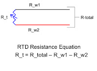
Since the RTD is a resistance device, the resistance of the wires used to connect the RTD to the measurement meter introduces errors and must be known. This is the reason a third (or fourth), wire is used.
 |
| 3rd wire used to cancel wire error |
Then the meter reads the resistance of one of the common wires, the RTD, and the non-common wire to determine Rtotal
 |
| Meter reading 2 common wires |

Rt = Rtotal – Rwire