Tuesday, March 12, 2019

Theory of RTD Operation

Theory of RTD OperationAn RTD is a temperature measuring device that changes resistance with temperature change, rather than changing voltage, as with a thermocouple.

Most commonly used is the platinum 100 ohm RTD because of their stability in air and linearity. Their resistance is 100 ohms @ 0 Deg.C and increases with temperature.

Theory of RTD OperationCommon terms associated with RTD’s are temperature coefficient or alpha, and tolerance class.

Alpha is ohms per ohm per Deg.C.
The average resistance change per unit of temperature from boiling point to ice point of water:

  • Rboiling – Rice point/100deg/100ohms
  • 138.5 – 100.0/100/100 = .00385


Tolerance class is the amount an RTD will differ from the standard resistance curve per Deg.C.

  • Class A (+/- .15 + .002*t)
  • @ temp of 100DegC = +/- .35DegC

When ordering an RTD, a tolerance class will be part of the order, dependent on the application. IEC 751 stipulates that the RTD be marked with their nominal R0 value, their tolerance class, the wiring configuration and the temperature range.
Theory of RTD Operation
3-wire configuration

  • Pt100 / A / 3 / -100/+200  = Platinum 100 Ohm / Class A / 3-Wire / -100 to +200 Deg.C
The most common RTD configuration is the 3-wire type. This configuration is more than adequate for 99.9% of applications. If absolute accuracy is needed, a fourth wire can be introduced, but rarely is it worth the added cost.
Theory of RTD Operation
2-wire configuration

Another configuration is a two wire RTD with a stand-alone loop. (Probably rarely used today).

Since the RTD is a resistance device, the resistance of the wires used to connect the RTD to the measurement meter introduces errors and must be known. This is the reason a third (or fourth), wire is used.

Theory of RTD Operation
3rd wire used to cancel wire error
First the meter reads the resistance of the two common wires to determine the value of Rwire. For a three wire RTD, it is assumed that this resistance is the same as that of one common and one non-common wire.

Then the meter reads the resistance of one of the common wires, the RTD, and the non-common wire to determine Rtotal

Theory of RTD Operation
Meter reading 2 common wires
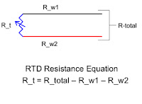
Meter electronics and software then subtract Rwire from Rtotal to get Rt which is then converted to a temperature.


Theory of RTD Operation


Rt = Rtotal – Rwire


Thursday, February 28, 2019

Theory of Thermocouple Operation

  • A thermocouple is a simple temperature measurement device consisting of a junction of two dissimilar metals.
  • Contrary to popular belief, the voltage measured (and converted to a temperature) is not a function of the junction alone. Rather it is the temperature difference (or gradient) between the junction (or hot), end and the reference (or cold), end.
  • A thermocouple circuit whose junction and reference are the same temperature will measure no temperature (0V).
  • If this were not true, we could create a self-sustaining voltage generator using a thermocouple, a resistive load and an oven, that would require energy only at start-up.
Theory of Thermocouple Operation

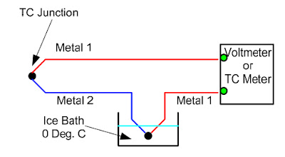
The temperature equation for the simplest of thermocouple circuits shown above is:

T = Tjunc – Tref

Where T is the desired measurement, Tjunc is the hot junction temperature and Tref is the reference
temperature, or cold end.

For simplicity’s sake, we use T, Tjunc and Tref here, but in reality these are voltages that are later converted to a temperature.

Cold Junctions
Theory of Thermocouple Operation

The temperature equation for this diagram is:
T = Tjunc – Tcj1 – Tcj2

A fundamental problem when using thermocouples is the fact the when connected to a measurement device (voltmeter or TC meter), a third metal is introduced (the connecting terminals), and two more thermocouple junctions are created. These adversely affect the temperature being measured. The new, (and unwanted), junctions are referred to as “cold junctions” and need some type of “cold junction compensation” in order to make accurate measurements.

In addition to the added variables in the previous equation, the temperature of the cold junctions
(reference end), is still not known. The following rule helps things out a bit:
  • If both TC connections to the meter are of the same metal or alloy, they cancel each other and have no affect on the measurement, as long both connections are at the same temperature (which can be assumed).
Since the definition of a thermocouple states that it must be of dissimilar metals, a second thermocouple must be introduced to the circuit to achieve this. This was the first of what is commonly called “cold junction compensation”

By adding a second series thermocouple suspended in an ice bath, the cold junctions at the meter are of identical metals and cancel each other. In addition, the temperature of the ice bath is known to be 0 Deg. C and becomes the reference end of the thermocouple.

The temperature equation is now simplified and once again becomes:

T = Tjunc – Tref
Theory of Thermocouple Operation
While the ice bath reference junction eliminates errors, it is clearly impractical for most, if not all applications.  Fortunately, all of today’s thermocouple read back options (meters, chart recorders, PLCs, etc.), come equipped with cold junction compensation, usually a thermistor and associated circuitry and software. By taking the cold junction worries out of the picture, the thermocouple remains one of the simplest, most robust and widely used temperature measurement devices around.

Monday, February 25, 2019

Thermocouple Wire Insulation Materials

Thermocouple Wire Insulation

Insulated thermocouple wire is single pair wire that can be made into a thermocouple. Thermocouple wire is available with many types of electrical insulation. The choice of the proper insulation material is based on cost, temperature rating, chemical & UV resistance and wear resistance. Below is a run-down of the most common thermocouple wire insulation materials.

Nylon
  • Suggested operating range: -85°F to 250°F (-65°C to 121°C)
  • Nylon provides high tensile, impact and flexural resistance.  It has excellent resistance to abrasion and is unaffected by most alkalis, oil, grease, dilute mineral acids and most organic acids.  It is inert to most organic solvents including hydraulic fluid and aviation oil. The individual conductors and outer jacket are extruded.
Fluorinated Ethylene Propylene (FEP) 
  • Suggested operating range: -90°F to 400°F (-67°C to 204°C)
  • FEP retains useful strength and flexibility over broad ranges of environmental temperature or thermal aging. FEP is flame retardant and non-propagating in fire conditions. It is moisture and chemical resistant and accepted for use around food and pharmaceuticals. The individual conductors and outer jacket are extruded.
Perfluoroalkoxy (PFA) 
  • Suggested operating range: -328°F to 500°F (-200°C to 260°C)
  • Flame retardant PFA provides flexibility and toughness with stress crack resistance, resistance to weather, non-aging characteristics and a low coefficient of friction.  PFA also provides outstanding electrical characteristics, as well as resistance to virtually all chemicals.  The individual conductors and outer jacket are extruded.
Tetrafluoroethylene (TFE) 
  • Suggested operating range: -328°F to 500°F (-200°C to 260°C)
  • TFE is flame retardant (passes IEEE 383 & VW-1 flame tests) and has excellent solvent and abrasion resistance.  TFE is unaffected by long term exposure to virtually all chemicals and solder iron temperatures. The individual conductors and outer jacket are insulated with TFE Tape.
Polymide Tape (Kapton) 
  • Suggested operating range: -400°F to 600°F (-240°C to 315°C)
  • Kapton is extremely tough.  It has excellent abrasion, impact and cut through resistance, very high resistance to oxidative degradation, weathering, and all chemicals except strong bases.  Kapton also offers high dielectric strength and insulation resistance.  Kapton does not support combustion; even at extremely high temperatures, it decomposes slowly without visible burning.  It is also resistant to radiation. The individual conductors and outer jacket are insulated with Kapton Tape.
Fiberglass 
  • Suggested maximum operating temperature: 900°F (482°C) continuous 1000°F (538°C) single exposure {Impregnation maintained to 400°F (200°C)}
  • Fiberglass insulation, with the special binder impregnation, offers good moisture and chemical resistance, as well as good abrasion resistance.  Typical applications include aerospace, foundries, heat treating, plastics industry and a wide variety of other uses.
  • Hi-Temp Fiberglass - Suggested maximum operating temperature: 1300°F (704°C) continuous, 1600°F (871°C) single exposure {Impregnation maintained to 400°F (200°C)}
For more information about thermocouple wire insulation materials contact Duro-Sense Corporation by calling 310-533-6877 or visiting https://duro-sense.com.

Friday, February 15, 2019

Temperature Sensing IS Rocket Science


Duro-Sense Corporation provides the precision temperature sensors to the aerospace, aviation, and space industries. Duro-Sense engineers bring proven solutions to your most difficult problems. Their R&D department is staffed with some of the industry's most qualified people, working in the most modern facilities to help advance the state of the art in temperature measurement.

Thursday, January 31, 2019

Thermocouples

thermocouple circuit
Diagram of a thermocouple circuit.
A thermocouple is a temperature measurement sensor. Thermocouples are made of two different metal wires, joined to form a junction at one end. The connection is placed on the surface or in the measured environment. As the temperature changes, the two different metals start to deform and cause resistance changes. A thermocouple naturally outputs a millivolt signal, so that the change in voltage can be measured as the resistance changes. Thermocouples are desirable because they are extremely low cost, easy to use and can provide precise measurements.

thermocouple
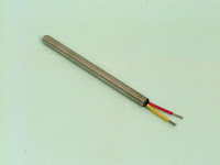
Typical sheathed thermocouple.
Thermocouples are produced in a variety of styles, such as sheathed, washer type, bayonet,  mineral insulated, hollow tube, food piercing, bare wire thermocouples or even thermocouple made from thermocouple wire only.

Because of their wide range of models and technical specifications, it is extremely important to understand their basic structure, functionality and range in order to better determine the right thermocouple type and material for an application.

Operating Principle

When two wires consisting of different metals are connected at both ends and one end is heated, a continuous current flows through the thermoelectric circuit. If this circuit is broken in the center, the net open circuit voltage (Seebeck Effect) depends on the temperature of the junction and the composition of the two metals. This means that a voltage is produced when the connection of the two metals is heated or cooled that can be correlated to the temperature.

Contact Duro-Sense Corporation with any questions about applying industrial and commercial thermocouples.

Duro-Sense Corporation
https://duro-sense.com
310-533-6877

Monday, January 28, 2019

Where to Mount Industrial Temperature Transmitters?

Temperature TransmittersIn an industrial plant, where there are normally long distances between the measuring points and the receiving instrumentation, some important aspects regarding the location of the transmitters can be mentioned.

There are basically three different locations for the mounting of the temperature transmitters:

  • In-head mounting - inside the connection head of the temperature sensors.
  • Field mounting – close to the temperature sensors.
  • Central mounting - in the vicinity of the control room

In-head mounting

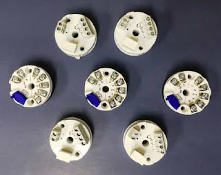
The transmitters are mounted directly inside the connection head and are normally replacing the terminal block.  This way of mounting normally offers the biggest advantages. It is however necessary to be aware of the environmental influence (mainly the temperature) on the measurement accuracy.

Advantages
  • Maximum safety in the signal transmission. The amplified signal, e.g. 4- 20 mA, is very insensitive to electrical disturbances being induced along the transmission cable.
  • Cost savings for the transmission cables. Only two leads are required if a 2- wire transmitter is used.
  • Cost savings for installation. No extra connection points because of the transmitter.
  • Cost and space savings. No extra housings or cubicles are needed.
  • Field instruments, e.g. indicators, can easily be installed, also at a later stage without redesigning the measuring circuits.
Disadvantages
  • The ambient temperatures can be out- side the allowed limits for the transmitters.
  • The ambient temperature influence on the measuring accuracy has to be considered. 
  • Extreme vibrations might cause malfunction of the transmitters.
  • The location of the temperature sensor can give maintenance problems.

Field mounting

The transmitters are either mounted directly beside the temperature sensors or in the vicinity of the sensors. Often more than one transmitter is mounted in the same field box.

This method is more expensive than In-head mounting, but otherwise a good alternative offering most of the advantages of In-head mounting without the disadvantages mentioned above.

Advantages
  • High safety in the signal transmission. The main part of the signal transmission is made with an amplified signal.
  • No extreme temperatures or vibrations exist. This facilitates accurate and safe measurements.
  • Cost savings for transmission cables.
  • A wider selection of transmitters is available. DIN rail transmitters can also be used.Field instruments can often be installed easily.
  • Maintenance can normally be carried out without problems.
Disadvantages
  • Higher installation costs compared to In-head mounting.
  • Costs and space requirements for transmitter boxes or cubicles.

Central mounting

In this case, the transmitters are placed in the vicinity of the control room or in another central part of the plant They are often mounted inside cubicles, and/or closed rooms. The ambient conditions are normally very good and stable.

This method offers the most convenient conditions for maintenance and the best possible environment for the transmitters. There are on the other hand some disadvantages that should be considered.

Advantages
  • Convenient conditions for installation, commissioning and maintenance.
  • Minimum risk for environmental influences (e.g. temperature influence).
Disadvantages
  • Reduced safety in the signal transmission. The low-level sensor signal is rather sensitive to electrical disturbances being induced along the trans- mission cable.
  • Relatively high costs for cabling. T/C measurements require compensation or extension cables all the way to the transmitters. RTD measurements with high accuracy should be done in 4-wire connection to get rid of the lead resistance influence.
  • Costs and space requirements for cubicles or frames.
  • Rather complicated and expensive to connect field instruments, e.g. indicators.

For more information on using temperature transmitters, contact Duro-Sense by calling 310-533-6877 or by visiting https://duro-sense.com.